The demands of working with large assemblies are constantly increasing. To push the limits and improve modeling efficiency, many factors must be considered. This article introduces the skeleton top-down design method - a powerful approach that streamlines the design process. By adopting this method, you’ll gain better control over your models and make it easier to reuse and adapt existing designs.
It’s important to understand that skeleton top-down design is not a specific set of commands in Inventor, but rather a methodology, a way of thinking and structuring your models. The key idea is to gather all known design parameters into a central “skeleton” model. This skeleton then serves as the foundation for subassemblies and individual parts.
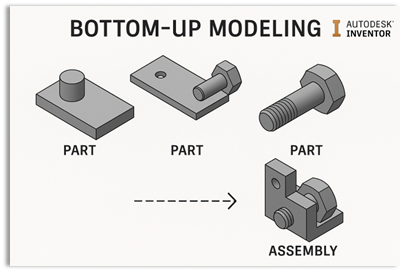
In Inventor, we typically refer to two main assembly strategies: bottom-up and top-down modeling.
Bottom-up modeling is the traditional method. You begin by creating individual parts, then assemble them using constraints to form subassemblies. These subassemblies are then inserted into higher level assemblies, working your way up to the top-level assembly. While straightforward, this approach often creates complex interdependencies between parts and assemblies. These cross references can make the model fragile and difficult to modify, especially when referenced geometry is deleted or changed.
A simple analogy is building a house of cards. You start at the bottom, leaning cards against each other, building layer by layer. Each new card relies on those below it for support. If you later try to replace one of the base cards, the entire structure is at risk because of those dependencies.
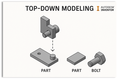
Top-down modeling, on the other hand, starts with defining the result. All known design intent and structure is captured in a skeleton model, which serves as a reference for the subassemblies and parts. This approach results in fewer conceptual files, a clear overview of the design intent, and a much more stable model. It simplifies design changes, speeds up updates, reduces memory load, enhances collaboration, and improves overall design efficiency.
Returning to the card house example: in a skeleton-based top-down approach, you would begin by modeling a foundation that represents the final layout of the card house. Each individual card is then created based on this foundation, receiving its size and placement from the skeleton. This way, cards are independent of one another and only reference the central skeleton. If you need to replace a card, it’s easy, there are no unstable dependencies between the cards themselves.
Overview Skeleton Modeling
In Autodesk Inventor's assembly design, skeleton modelling is a technique used to create a master model that drives the geometry of an entire assembly. The skeleton acts as a reference structure that ensures consistency and ease of updates across all parts. Sub-skeletons further refine this approach by organizing complex designs into manageable sections.
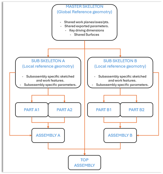
A master skeleton typically contains:
- Reference geometry such as sketches, work planes, axes, and points that define critical dimensions and relationships.
- Key driving dimensions that control multiple components.
- Surface used for defining interfaces between parts.
Sub skeletons are used within subassemblies and may:
- Define local relationships and constraints within a portion of the assembly.
- Inherit references from the main skeleton but allow for modular control.
- Simplify the design process for large or complex assemblies by segmenting the master model.
In Inventor’s skeleton modelling workflow, parts and sub-assemblies derive their geometry and positioning from the skeleton. The skeleton file contains sketches and reference geometry that define the shape and location of features in the assembly. When creating a new part in a skeleton-driven design, you derive or copy relevant skeleton geometry into that part. For example, projecting a skeleton sketch or using the derive command to import geometry. This means the part’s features (like extrusions, holes, etc.) can be built on top of lines, points, or surfaces defined in the skeleton. As a result, the skeleton directly controls the part’s geometry: if a dimension or shape in the skeleton changes, the derived features in the part update accordingly.
Not only shape, but assembly relationships (how parts fit together) are controlled by the skeleton as well. Often, the skeleton is placed at the origin of the top-level assembly, and all derived components are automatically grounded to that origin. This common origin approach means parts share a coordinate system and don’t require many mates or constraints for positioning. They’re essentially pre-aligned by the skeleton’s geometry. In cases where constraints are needed, designers frequently constrain parts to skeleton reference geometry (like mating a part face to a skeleton work plane or aligning a hole to a skeleton axis) instead of part-to-part constraints. Using stable reference items (work planes, axes, points) from the skeleton yields very robust assemblies. These references are less likely to break, and they carry clear intent. In fact, work geometry in the skeleton can serve as anchors for sub-assembly components, ensuring consistent alignment; for example, skeleton work axes can define the centreline for shafts or holes in multiple parts.
Critically, any updates to the skeleton will ripple through the assembly. Inventor maintains associative links between the skeleton and the derived parts. If you need to modify the design (say change a key dimension or reposition a feature), you simply edit the skeleton part. When the assembly is updated, all components that reference that skeleton adjust to the new skeleton geometry. Autodesk’s documentation emphasizes this single-point-of-edit advantage: to change the assembly, edit the skeleton part, then update the assembly to reflect the changes in all components affected by the skeleton. In essence, the skeleton drives both part geometry and assembly layout, acting as the master reference that holds the assembly together.
For large or complex projects, it’s common to use a main (master) skeleton at the top level and additional sub-skeletons for various sub-assemblies. A sub-skeleton is essentially a skeleton part that belongs to a portion of the design (a subassembly) rather than the whole product. These sub-skeletons are usually derived from the main skeleton so that they inherit the relevant geometry and parameters needed for their portion of the design. Autodesk recommends deriving additional skeleton parts from the master skeleton to represent or add details for sub-assemblies, instead of packing everything into one huge skeleton. In practice, this means you take the master skeleton and create a new part (sub-skeleton) that pulls in only the information needed for that sub-assembly. For example, if you have a master skeleton for an entire machine, you might derive a sub-skeleton for the frame assembly, another for an actuator assembly, etc., each receiving just the sketches, surfaces, and parameters needed for that section.
The connection between the main skeleton and a sub-skeleton is an associative one, the sub-skeleton is like a child of the master. Because the sub-skeleton is derived from the main, it remains linked. Any changes made at the top (master skeleton) level will update the sub-skeleton, which in turn updates the parts built from that sub-skeleton. This hierarchy ensures a controlled cascade of design updates. It effectively partitions the design: the main skeleton governs high-level dimensions/locations, while each sub-skeleton can introduce more detail or local refinement for its subassembly. The sub-skeleton may add its own sketches or parameters that only matter to that subassembly, but it still relies on the master for the global reference. This keeps the entire assembly coordinated.
Using sub-skeletons is also a strategy for managing complexity and performance. By offloading details into sub-skeleton files, the master skeleton doesn’t become overly cluttered with every sketch or feature in the project. Each sub-assembly team can work with their sub-skeleton in relative isolation and then integrate with the master layout. It also avoids passing irrelevant data down to parts that don’t need it. For instance, you might have certain parameters in the master skeleton that only one subassembly cares about; instead of pushing those through to every part, you derive them into that sub-skeleton only. This way, predefined parameters can be spread to sub-skeletons only for the portion of the design that uses them, preventing unnecessary clutter in other areas. In short, the main skeleton provides the big picture, while sub-skeletons break the big picture into manageable chunks – all linked together so the design intent remains consistent at every level.